Built from parameters
Describe the plate and its internal flow path in the dedicated Creator.
 ASCENTRACFD SOFTWARE
ASCENTRA / PILLOW PLATE CFD ANALYST
Define the weld layout, generate the plate geometry and explore flow and heat transfer in a dedicated simulation workflow.

01 / A CONNECTED WORKFLOW
Keep plate geometry, operating conditions and result inspection together. Review supported design alternatives under consistent conditions.
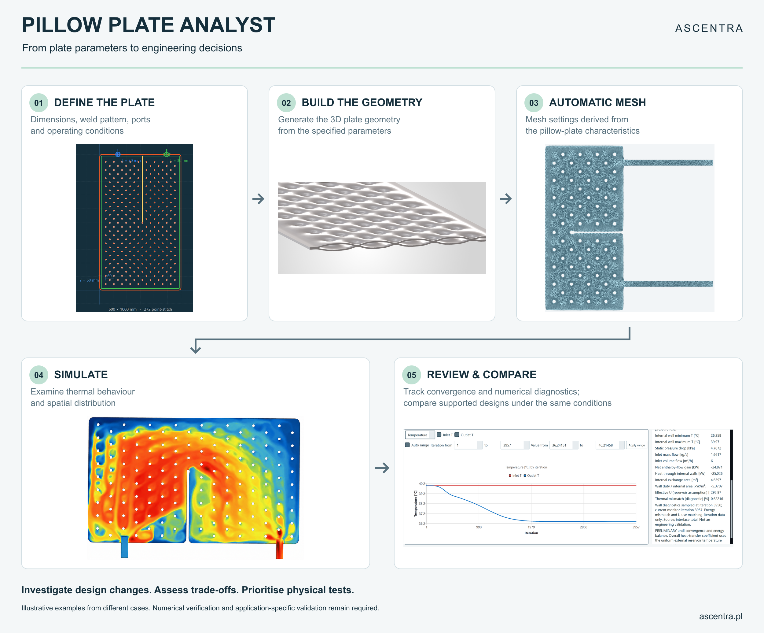
The overview combines examples from different cases. Numerical verification and application-specific validation remain necessary.
02 / PARAMETRIC GEOMETRY
Set plate dimensions, sheet thicknesses, channel height, point-weld diameter and spacing. Position connections and guiding seams, then generate the three-dimensional geometry with a smooth profile near the welds.
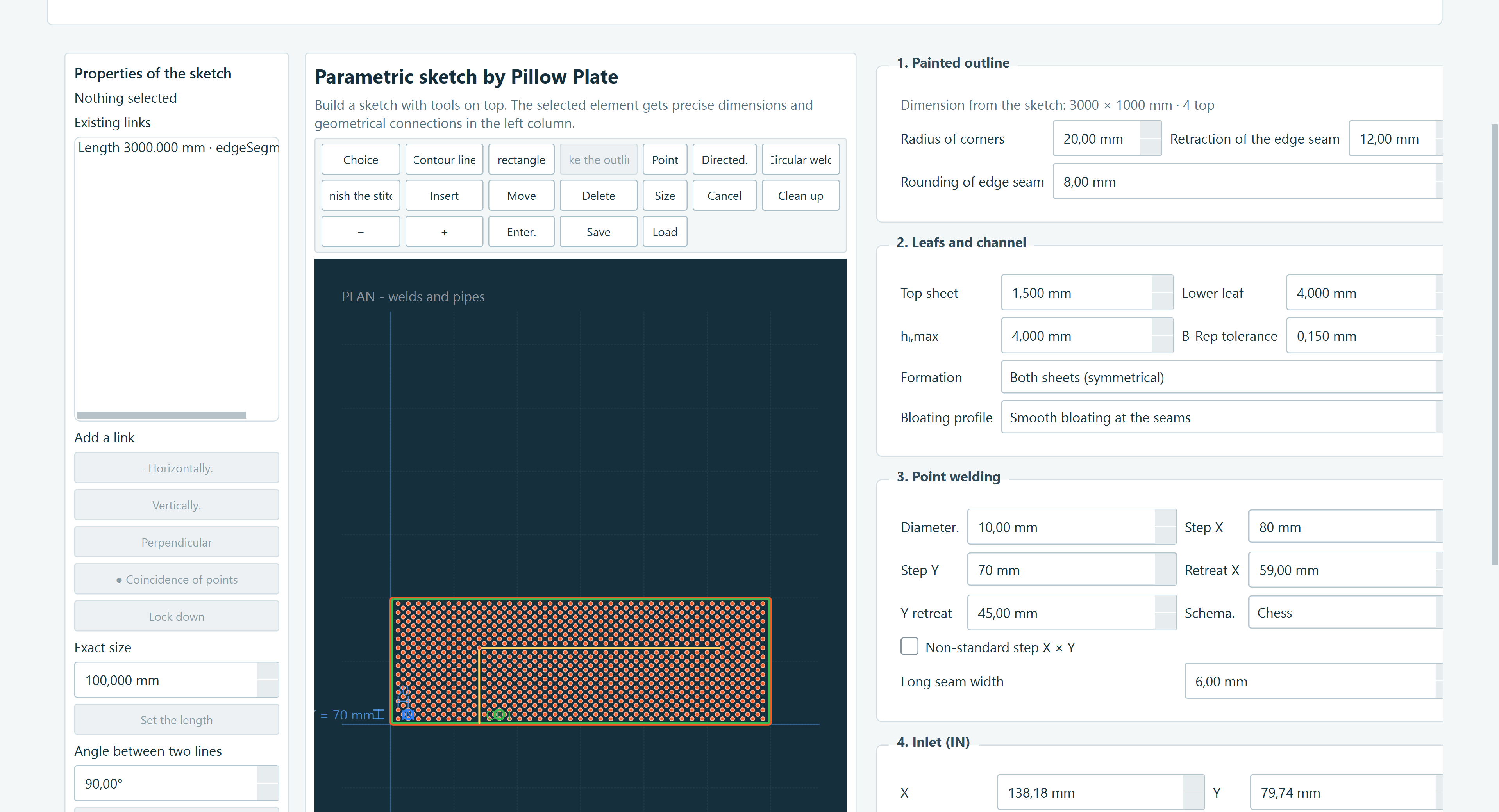
Describe the plate and its internal flow path in the dedicated Creator.
Use the CAD-adapted workflow after geometry generation, with mesh checks before calculation.
Reopen mesh settings and rebuild when the study needs a different resolution.
Use the fluid library or enter custom liquid and gas properties for the selected conditions.
03 / FIELDS WITH CONTEXT
Explore temperature, velocity and pressure fields. Investigate how weld patterns, guiding seams and connections affect local behaviour.

04 / MONITOR AND DOCUMENT
Track inlet and outlet conditions, inspect numerical diagnostics and document the study in PDF and editable Word reports. A stable-looking curve alone is not proof of accuracy.


EXPERIMENTAL OPTION / TANK-WALL APPLICATIONS
Study internal channel flow and metal conduction with separate thermal conditions on the two outer faces. This option represents the surrounding media through heat-transfer boundary conditions instead of meshing an external fluid volume.
Assign product-side and ambient temperatures and select the medium for each side.
Use a measured coefficient or a supported design-point correlation. Automatic estimates require suitable fluid properties and operating assumptions.
Define density, heat capacity, viscosity and thermal conductivity. Save the properties with the project.
Experimental, steady reservoir approximation. Estimated coefficients remain fixed during a run. The model does not resolve tank mixing, curved-wall effects or the cooling time of a finite tank. Suitability must be assessed for the installation.
EVALUATION SCOPE
The current standard evaluation offer covers one plate up to 3 m² by length × width, subject to geometry and physics review. Larger geometries and experimental modes require an individual scope discussion. Structural certification and phase-change analysis are not included.
START A CONVERSATION
Request a demonstration or discuss a 14-day software evaluation. Share the geometry, operating conditions and engineering question you want to investigate.
Scope, availability and the evaluation start date are confirmed by email. Plate Bank enquiries concern a project in development.
support@ascentra.pl ↗